Design for 3D Printing: The 10 Rules That Actually Matter
Most 3D printing failures happen before the print starts. Learn the 10 design rules that separate prints that work from prints that fail.
Every year, the 3D printing industry publishes more design guides, and every year, the same mistakes show up on print beds everywhere. Warped overhangs. Walls that won't print. Parts that snap the first time you put load on them. The problem is not a lack of design rules. The problem is that most guides bury the important stuff under edge cases that do not matter for 95% of prints.
These are the 10 rules that actually matter. Not the complete list. The complete list is infinite and depends on your printer, your material, your environment, and your tolerances. But these are the rules that will get you from "this should work" to "this works" on the first try, most of the time.

1. Wall Thickness: Multiples of Your Nozzle
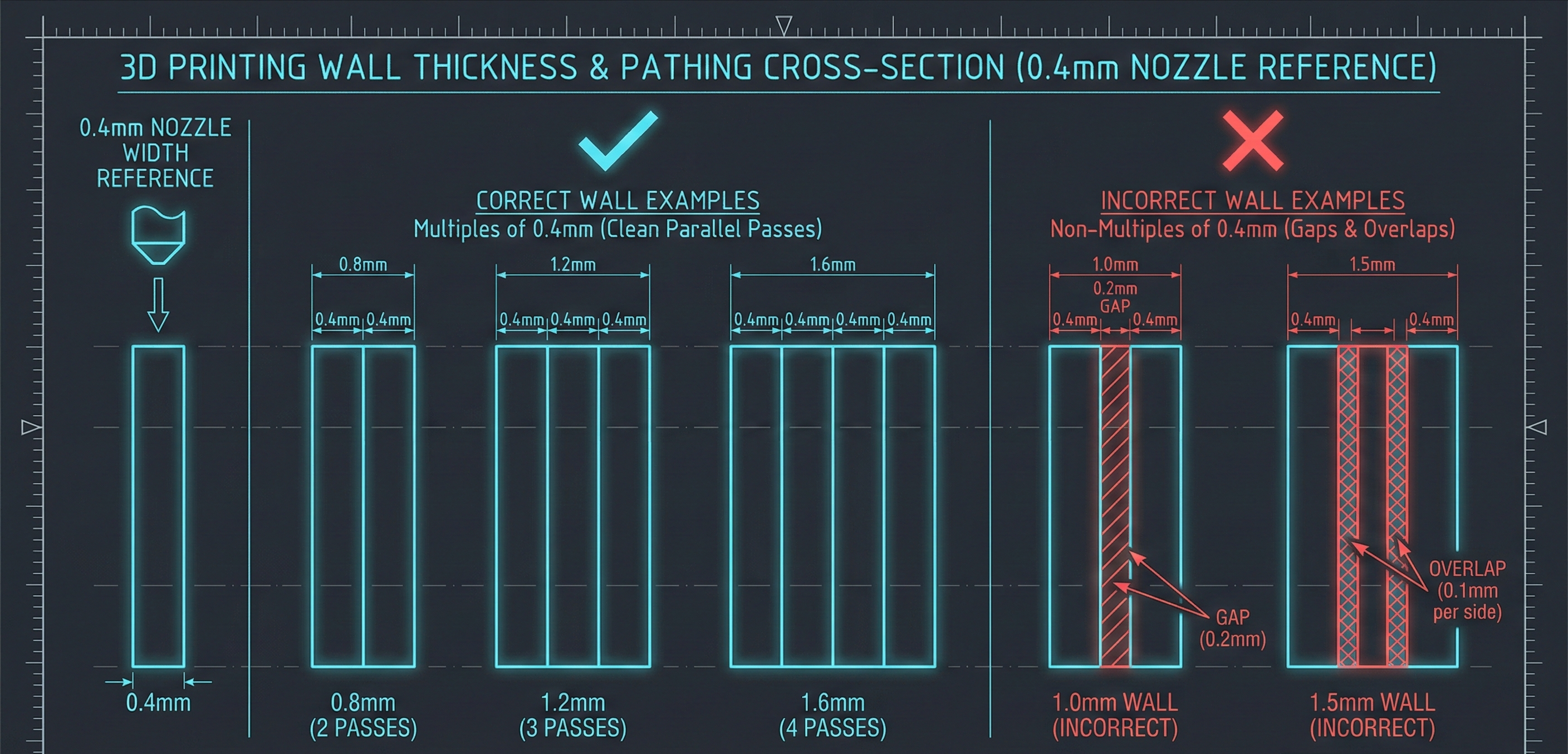
The wall thickness rule is simple math that people constantly ignore. Your walls should be whole-number multiples of your nozzle diameter.
If you are running a 0.4mm nozzle (most common), your wall thicknesses should be 0.8mm, 1.2mm, 1.6mm, or 2.0mm. Not 1.0mm. Not 1.5mm. When your slicer encounters a wall that does not divide evenly by the nozzle width, it has to either leave a gap or overlap the extrusion. Both options create weak spots.
For structural parts, aim for at least 1.2mm (three perimeters). For enclosures and non-structural components, 0.8mm works. Below that, you are asking for trouble.
This rule is the closest thing to a free lunch in 3D printing. It costs nothing, requires no special skills, and makes an immediate difference.
2. The 45-Degree Overhang Rule
Overhangs are features that extend horizontally beyond previously printed layers. The 45-degree rule exists because filament needs something to stick to.
Any surface that extends more than 45 degrees from vertical needs support. Any surface within 45 degrees will self-support because each layer has enough contact with the layer below to stay put as it cools.
The YHT test is a useful mental model: The letter Y has arms at 45 degrees and prints fine without support. The letter H has a horizontal bridge that may work depending on distance. The letter T has arms at 90 degrees and usually needs support or redesign.
If you can redesign your part to keep overhangs within 45 degrees, do it. Every support you eliminate is material saved, time saved, and post-processing work avoided.
3. Supports Are a Tax, Not a Feature
Support structures exist because designers asked for geometry that printers cannot produce unsupported. They are a necessary evil, not a design goal.
Every support you print is material you throw away. It is time your printer spends not making your part. And it is post-processing work you add to your build. Worse, supports leave marks where they contact your part, degrading surface finish in exactly the places you probably care about most.
Design your parts to minimize supports from the start. Sometimes that means splitting one complex part into two simpler parts that assemble later. Sometimes it means orienting the part differently on the build plate. Sometimes it means accepting a slightly different geometry that accomplishes the same function without the cantilever.
The best support is the one you never had to print.
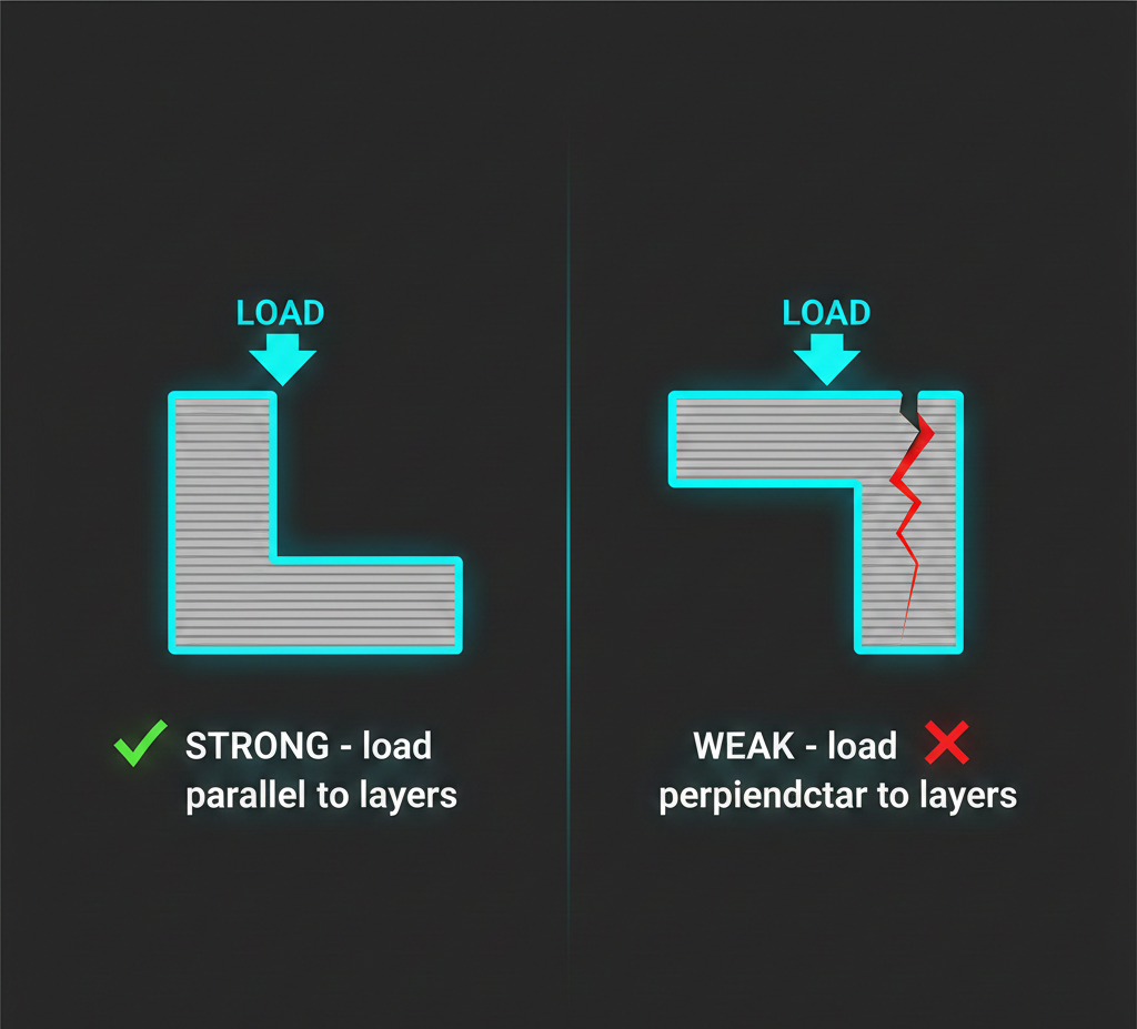
4. Orientation Is Load Planning
How you orient your part on the build plate determines how strong it will be under load. This is not mainly about aesthetics or print time. It is about where the part will fail when stressed.
Layer adhesion is the weak point in FDM printing. Bonds between layers are weaker than continuous extrusion paths within a layer. This means parts are weakest when forces try to separate layers, and strongest when forces run along layer lines.
If your part will experience tension or bending in use, orient it so load runs parallel to layers, not perpendicular. A bracket that holds weight should usually be printed so layers align with the load direction.
This rule alone can double the functional strength of a part without changing geometry or material.
5. Bridging Distance Matters
Bridging is what happens when your printer extrudes across open air between two supports, like printing the horizontal bar in the letter H. The printer stretches filament across the gap and hopes it does not sag too much.
Most printers can bridge about 10mm reliably. Beyond that, filament droops and you get ugly undersides or outright failures.
If your design requires a bridge longer than 10mm, you have three options: add internal supports that get removed later, redesign to break the bridge into shorter spans, or accept a rough underside. The first two options are usually worth it.
Bridge quality also depends heavily on cooling. If you are bridging, make sure your part-cooling fan is at 100% for that section.
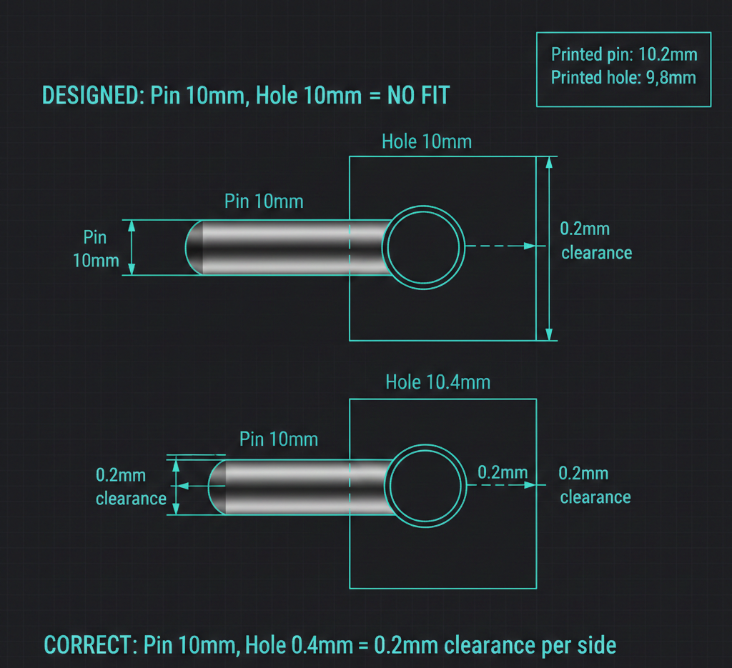
6. Mind the Gap: Clearance for Mating Parts
When you design parts that fit together, pins into holes, tabs into slots, hinges and joints, dimensions on screen will not match dimensions off your printer.
Material shrinks as it cools. Extrusion paths have width. Elephant's foot on the first layer adds material at the base. All of this means your 10mm hole might print as 9.8mm, and your 10mm pin might print as 10.2mm, and now nothing fits.
Standard practice for FDM is to design with 0.2-0.4mm clearance on each mating surface. A pin going into a hole should have the hole diameter 0.4mm larger than the pin for a typical fit. For loose fits (parts that should move freely), go to 0.5mm or more. For tight press fits, you might get away with 0.1mm plus finishing.
Test your tolerances. Every printer is different, and even the same printer varies with material and temperature. Print a tolerance test with different gaps, find what works for your setup, and use those numbers consistently.
7. Sharp Corners Concentrate Stress
Sharp corners in 3D prints are stress concentrators. When load is applied, forces focus at corners instead of distributing across the part, and that is where cracks start.
The fix is straightforward: fillet internal corners and chamfer external ones. A radius as small as 1-2mm on internal corners can improve strength significantly under load.
There is a 3D-printing-specific wrinkle: downward-facing fillets can create overhangs that need support. In that orientation, a sharp corner may print cleaner than a fillet.
The workaround is to use 45-degree chamfers on downward-facing edges. The chamfer follows the overhang rule and prints cleanly. You can also combine both approaches: chamfer downward faces and fillet upward faces.
8. Make It Watertight
A 3D model that looks solid on screen can still have invisible holes, gaps, and overlapping surfaces that make it unprintable. The technical term is non-manifold geometry, and it is one of the most common causes of confusing print failures.
Every surface needs to connect to adjacent surfaces with no gaps. Every edge should be shared by exactly two faces. No faces should be inside out. No surfaces should overlap or self-intersect randomly.
Most CAD and slicing software can check this. Meshmixer has an Inspector tool that finds and repairs holes automatically. PrusaSlicer and Cura also attempt repairs on import, but those repairs are not always what you intended.
If you are generating geometry programmatically, by code or by AI, watertight validation is even more important. It is easy for automated systems to produce geometry that looks right in preview but contains tiny topological errors. This is also where understanding BREP vs mesh becomes critical for manufacturing workflows.
9. Resolution Is a Tradeoff, Not a Setting
Layer height controls detail and layer-line visibility on curved surfaces. Lower layers increase detail, but print-time cost is linear: halving layer height roughly doubles print time.
For functional parts that do not need aesthetic finish, use the thickest layers your printer handles cleanly, often 0.28mm or 0.32mm. For parts where surface quality matters, drop to 0.16mm or 0.12mm. For very fine detail, 0.08mm is possible but slow.
Rule of thumb: use the largest layer height that still meets your real requirement. Many teams print functional prototypes at 0.12mm by habit, then wonder why iteration is slow. A bracket does not care about visible layer lines.
10. Infill Is Usually Overrated
The common instinct is to increase infill for strength. More material should mean more strength, right?
Not usually. Beyond about 20-25% infill, returns drop quickly. A part at 50% infill is not twice as strong as a part at 25% infill. It may be only modestly stronger while using much more material and time.
If you need stronger parts, increasing wall thickness (perimeters) is usually more effective than increasing infill. Four perimeters at 15% infill will often outperform two perimeters at 40% infill.
Reserve high infill for parts that need mass (ballast), parts that will be machined post-print, or parts under unusual loads. For most use cases, 15-25% with a strong pattern (gyroid, honeycomb) is enough.
---
What AI Changes
These 10 rules are exactly the kind of manufacturing knowledge traditional CAD leaves entirely to the designer. You design, slice, print, and if it fails because you missed a wall-thickness multiple or overhang angle, that is on you.
Code-driven workflows open a better path. If the system generating geometry understands these rules, it can enforce them automatically. An AI-generated mounting bracket can be constrained to nozzle-multiple walls, printer-safe overhangs, and practical mating clearances from the start.
This does not remove the need for engineering judgment. You still verify outputs. But it shifts the burden from remembering every constraint manually to validating constraints in generated outputs. That is a much better failure mode, and it will keep improving as code-based CAD systems mature and references become more stable (including persistent naming concerns described in the topological naming problem).
The rules are not going away. But who applies them, and when, is changing.
---
What design rule did you learn the hard way? Most people doing serious 3D printing have at least one "obvious in hindsight" failure. Share yours.---
Henqo generates manufacturing-ready BREP geometry from natural language, designs that can actually be made, not just rendered. Try it free.