The Hidden Cost of Mesh-Based Design Tools: Why Triangles Don't Cut It for Manufacturing
Mesh-based AI design tools promise speed but create hidden costs in manufacturing, editing, and precision. Learn why BREP geometry matters for real parts.
The AI design tool landscape is exploding. Text-to-3D generators can now produce visually impressive models in seconds. But there's a dirty secret the marketing demos don't show: most of these tools output mesh geometry—and that choice creates cascading problems the moment you try to actually make something.
If you've ever tried to machine an AI-generated model only to have your CAM software reject it, or watched a 3D print fail because the wall thickness was impossible to verify, you've encountered the hidden cost of mesh-based design.
This isn't about meshes being "bad." They're excellent for rendering, games, and visual prototypes. The problem is that mesh geometry fundamentally lacks the information manufacturing processes need—and that missing information costs real time and money downstream.
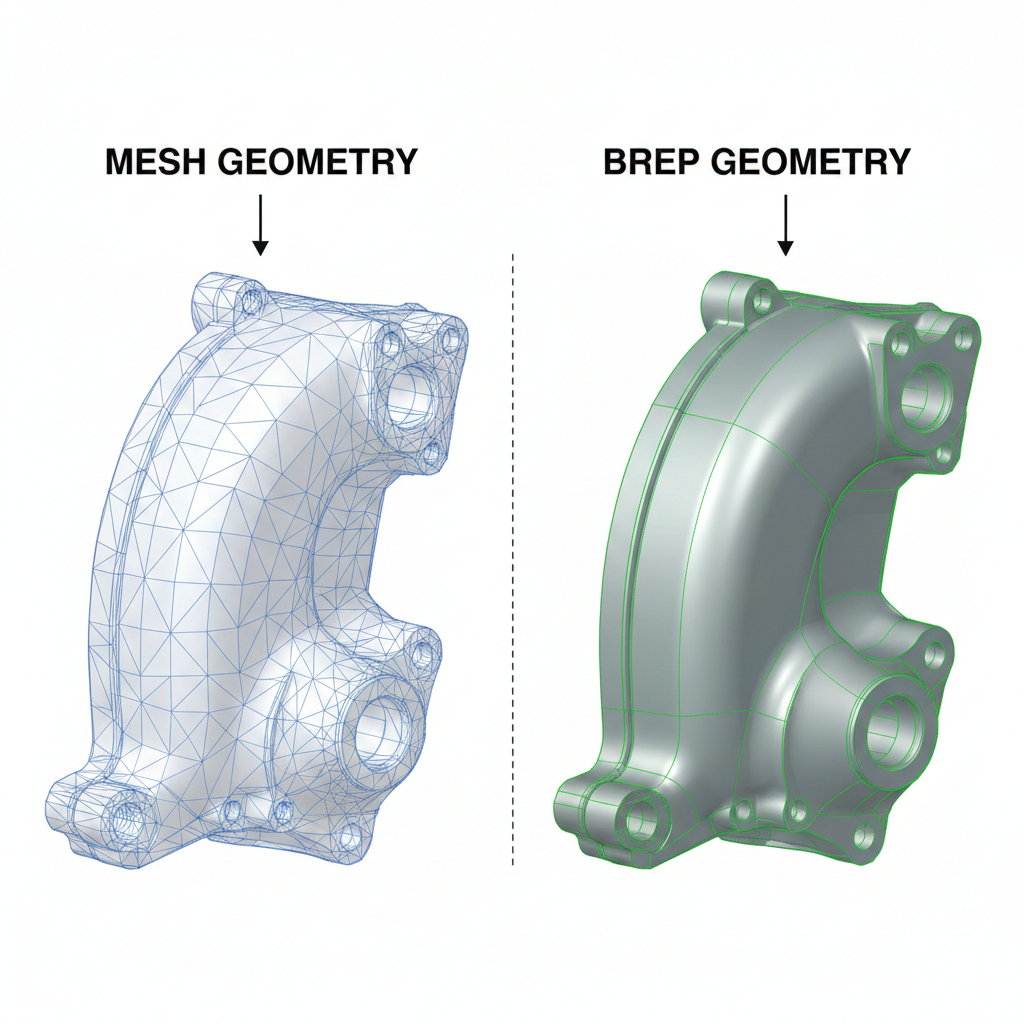
What's the Difference Between Mesh and BREP?
Before diving into costs, let's clarify the core distinction.
Mesh geometry represents surfaces as collections of triangles (or sometimes quads). An STL file—the most common mesh format—is essentially a list of triangle vertices. A simple cube requires 12 triangles. A sphere might need thousands to look smooth. BREP (Boundary Representation) defines surfaces mathematically. A cylinder isn't approximated by hundreds of tiny flat faces—it's described as an actual cylindrical surface with an exact radius, axis, and bounds. A sphere is a mathematical sphere. A plane is infinite precision, trimmed to boundaries.This difference sounds academic until you try to do something real with the geometry.
The Five Hidden Costs of Mesh-Based Design
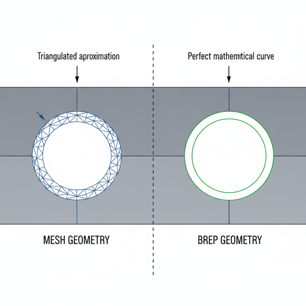
1. No Exact Dimensions—Ever
Mesh geometry approximates curves. Always. A 10mm diameter hole in a mesh file is actually a polygon—maybe a 24-sided or 48-sided approximation of a circle.
What does this cost you?
- CNC programming failures. CAM software often refuses to generate toolpaths from mesh geometry because it can't identify the "real" features. Is that a 10.0mm hole or a 10.02mm hole? The mesh doesn't know.
- Metrology nightmares. When your CMM tries to measure that hole, it can't find the true center because there isn't one—just vertex coordinates that approximate a circle.
- Tolerance ambiguity. You specified ±0.05mm on that feature. But the mesh itself has more deviation than that built in. Which tolerance matters?
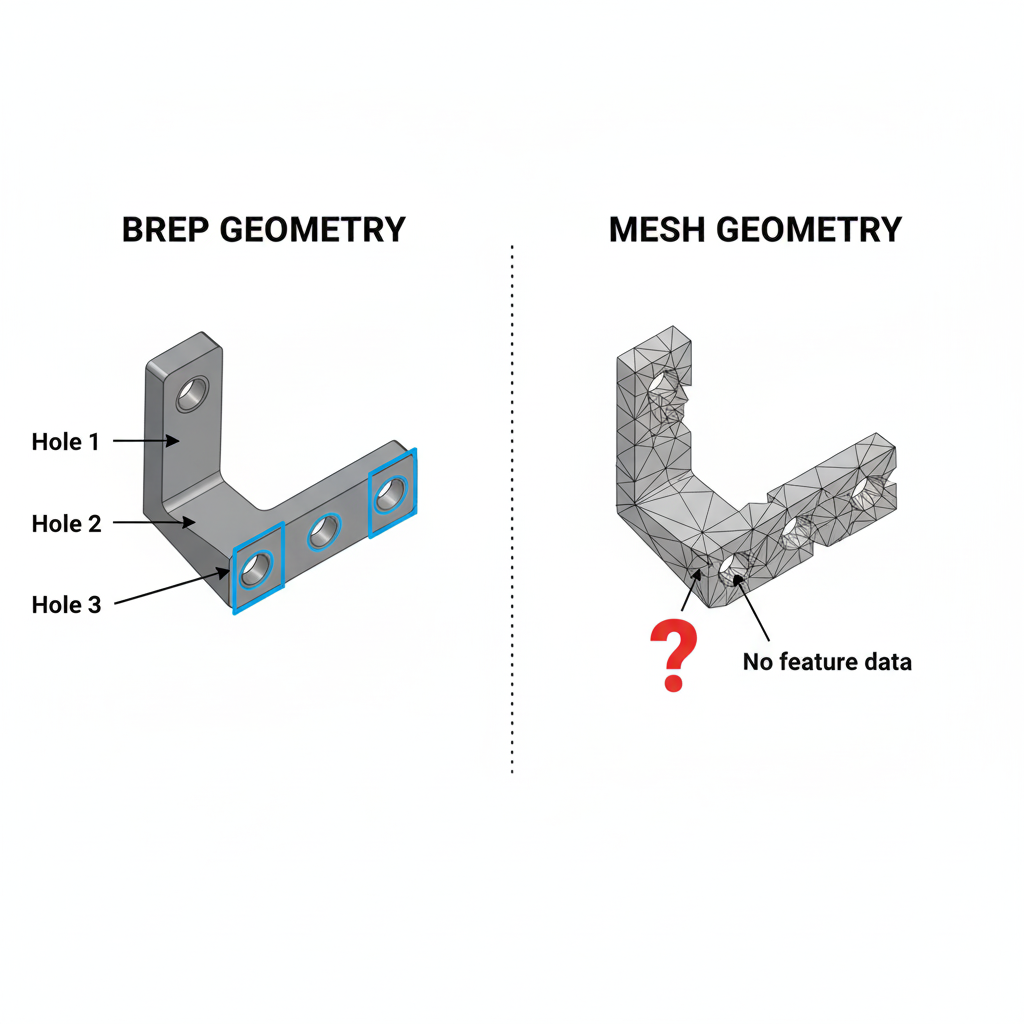
2. Manufacturing Processes Require Feature Recognition
Modern CAM software doesn't just generate toolpaths from raw geometry—it recognizes features. That pocket needs a roughing pass, then a finishing pass with a smaller tool. Those holes need a drill cycle. That slot needs a specific feed rate.
Feature recognition requires understanding what things are, not just their shape. BREP geometry carries this information:
- This face is a plane
- This face is a cylinder with radius 5mm
- This face is a cone with semi-angle 45°
At Henqo, our Build123d-based pipeline maintains full BREP topology. When we export a model, we generate a topology map that links each triangle in the visualization mesh back to its originating BREP face. The system knows that triangle cluster represents a cylindrical surface with a specific radius—not because it guessed, but because it generated that cylinder mathematically.
3. The "Repair" Tax
Mesh files frequently have problems: gaps, overlaps, inverted normals, non-manifold edges. These issues are so common that "mesh repair" is an entire software category.
The mesh repair tax shows up everywhere:
- Time spent fixing files before they can be used downstream
- Software costs for repair tools (some charge per file)
- Quality uncertainty about whether repairs preserved intent
- Print failures when repairs weren't quite right
Our geometry analyzer extracts facts like solid count and manifold validity during generation. If the LLM produces disconnected geometry or non-manifold topology, the system catches it immediately—not after export to STL.
4. No Parametric Editing
Changed your mind about that hole diameter? With BREP-based parametric CAD, you change a number and the model regenerates.
With mesh? You're sculpting vertices. Or starting over.
This isn't just inconvenient—it's a workflow killer for iterative design. Real engineering involves constant refinement: test, measure, adjust, repeat. If every adjustment requires regenerating the entire model from scratch (or manually editing thousands of triangles), iteration grinds to a halt.
Even "simple" changes become expensive:
- Making a part 5mm longer? You'd need to scale or insert geometry—neither preserves original intent.
- Changing fillet radii? The triangles encoding those fillets don't know they're fillets.
- Adjusting hole patterns? Good luck identifying which triangles represent holes.
5. Face Selection Doesn't Exist
Try to select "the top face" of a mesh model. You can't. There is no top face. There are triangles that happen to be on top, but the mesh has no concept of faces as coherent entities.
This matters for:
- Applying constraints in assemblies (mate this face to that face)
- Specifying manufacturing operations (finish this surface to Ra 0.8)
- Adding features (put a hole in the center of this face)
- Communicating design intent (this is the mounting surface)
>Z (top face), <X (left face), %Cylinder (cylindrical surface)—that humans and AI can both understand. When you say "put a hole in the top face," the system knows exactly what you mean.
The Real-World Cost: A Case Study
Consider a simple bracket: a flat plate with mounting holes and a bent flange. An AI text-to-3D tool generates a mesh version in seconds.
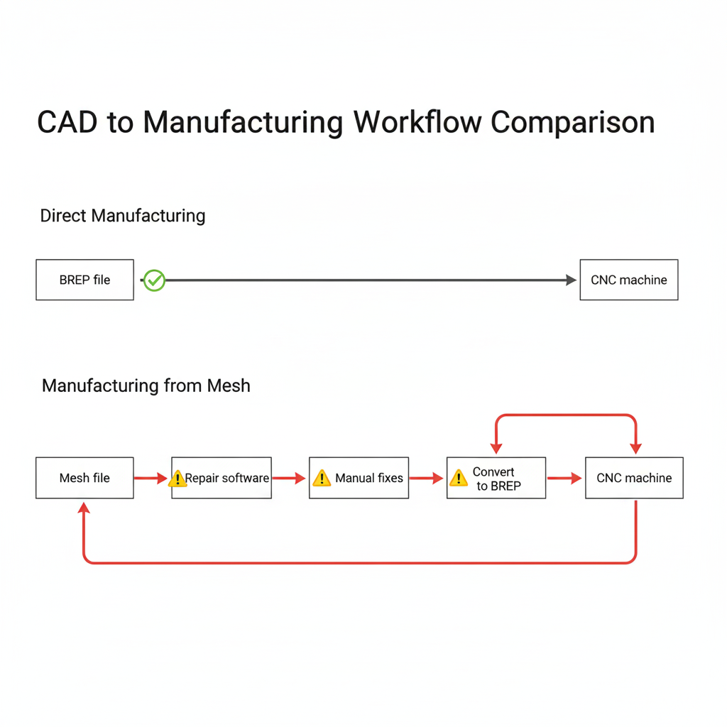
The mesh workflow's "free" generation time gets buried in downstream costs that multiply with every revision.
Why Do So Many AI Tools Use Mesh?
The answer is technical convenience.
Training AI models on mesh generation is easier than BREP generation:
- Meshes are just coordinate lists—simple data structures
- Rendering engines already work with meshes
- Datasets of mesh models are abundant
- The math is conceptually simpler
- Exact curve and surface mathematics
- Topological relationships (which faces share which edges)
- Solid modeling operations (unions, intersections, cuts)
- Kernel-level validation rules
The Path Forward: BREP-Native AI
The solution isn't to abandon AI-assisted design. It's to build AI that outputs manufacturable geometry from the start.
This is why Henqo generates BREP geometry natively using Build123d and the OpenCascade kernel. When you describe a part, the AI doesn't generate triangles and hope for the best. It constructs actual solid modeling operations—extrusions, revolutions, boolean operations—that produce mathematically exact geometry.
The result is STEP files that any CAM software can use. Faces with identity. Features that can be recognized. Geometry that means something to manufacturing equipment.
Evaluating AI Design Tools: Questions to Ask
When evaluating any AI design tool, ask these questions:
The answers reveal whether the tool was built for rendering or for making things.
Conclusion: Choose Your Geometry Wisely
Mesh-based design tools have their place—visualization, game assets, artistic sculpting. But for engineering applications where geometry becomes physical, the hidden costs compound quickly.
Manufacturing requires exact dimensions. CNC and metrology require feature recognition. Iteration requires parametric editing. Assembly requires face selection. Mesh geometry provides none of these.
The extra complexity of BREP-native AI isn't overhead—it's investment in geometry that actually works downstream. When your "cheap" mesh model costs hours in conversion, repair, and rework, was it really cheap?
Ready to try AI-generated CAD that outputs real STEP files? Try Henqo free →